
Why Cantilevered Plant Box Collars Are Not ASTM Specification
By Jan Johnson
Director Sky Jumpers Vertical Sports Club, Olympic Medalist, Former WR holder, Co-inventor Vault Box Safety Collar(patented), Director Pole Vault Safety Certification board
Edited by Eddie Seese
Founding Chairman of ASTM subcommittee F 08.67 Pole Vault, Emeritus Level USATF Certified Official, Member Pole Vault Safety Certification Board, USATF level 2 coach, National level USATF official
Recently we were concerned and confused by an advertisement that we saw for a new pole vault box collar. The advertisement states that the collar meets the ASTM specification required by both the NCAA and NFHS rules. Our interpretation of the ASTM box collar F2949 specification and the NCAA and NFHS rules, however, leads us to believe that it does not.
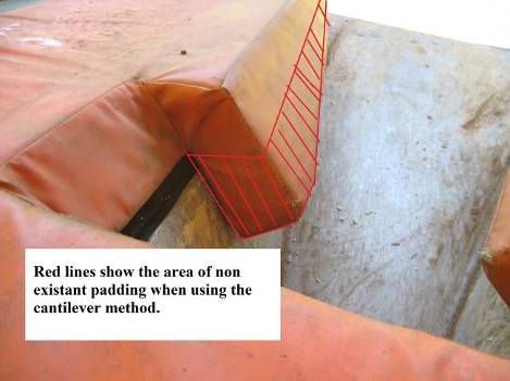
Although the body and arms of the product advertised may meet or exceed the force impact testing requirements of ASTM F2949, the photograph in the advertisement makes it look as though the new collar does not have wings extending down into the plant box. And since the ASTM F2949 testing protocol requires wings to be tested, practically and realistically, unless there are facts of which we are unaware, it seems unlikely that the product can meet the ASTM F2949 standard. Simply stated, the cantilevered collar advertised does not appear to meet the dimensional or structural requirements defined in ASTM Specification F2949 because it appears to lack wings extending down into the plant box.
Later in this document we have included many example pictures to help explain why cantilever padding was not included in the ASTM Specification. Additionally we have included text and diagrams directly from F 2949 for a clear understanding regarding what the ASTM committee that passed the specification had in mind.
The advertising for this new box collar seems to emphasize its force impact testing, but it seems that the collar does not meet the F2949 specified dimensions. The advertisement states that the product meets the NFHS rules and the ASTM Specification. Again, unless there are facts of which we are unaware, that advertisement does not appear to be accurate. It does not appear that a cantilevered collar, such as the one advertised, will meet the design requirements of the ASTM Specification. Although we have only seen pictures, not an actual sample of the cantilevered collar in the advertisement, the advertisement photograph we have seen makes it look as though the collar lacks the padding of the inner upper box walls (i.e., wings) necessary to comply with the design requirements of the ASTM F2949 Specification.
Since Dave Nielson’s cantilevered collar facebook video first appeared in 2012, the ASTM Pole Vault equipment committee has discussed at length, on several occasions, the pros and cons of cantilevered collars. At no time was this method ever considered a real possibility for specification. Our recollections of the committee discussions are that most committee members who discussed that issue concluded that the drawbacks of such a design outweigh the benefits. Additionally, we know of no scientific evidence or research and development information which supports the cantilevered method. Lastly, as a matter of legal concern, the advertised box collar may pose patent infringement concerns. In sum, we are concerned that the collar advertised may not provide the safety required by the ASTM Specification. Rather, we believe that a box collar that does in fact meet the ASTM F2949 Specification will provide the superior protection intended by both the NCAA and NFHS rule makers.
Cantilevered box collars can’t meet the ASTM testing protocol because they have no wings to test! The following essential definitions are directly from the specification. They are the key structural elements designed to improve safety (key phrases are in red).
F2949 definitions
“3.1.2 box collar body, n—the part of the pole vault box
collar that pads the horizontal surfaces around the rim of the
pole vault box and under the front buns.
3.1.4 box collar wing, n—the part of the box collar arm that
extends down the inner sidewall of the pole vault box. The box
collar wings provide protection and help to hold the box collar
in place.
Box
3.1.12 sidewalls, n—the left and right walls of the pole vault
box.”
“REQUIRED testing locations F2949:
9.1.5 Impact tests shall be completed on the pole vault box collar at the following four locations in any order:
9.1.5.1 On the centerline of the box collar 13 cm (5 in.) behind the rear edge of the box collar cutout;
9.1.5.2 On either box collar arm, 69 cm (27 in.) behind the front edge of the box collar arm and midway between the lateral edge of the box collar arm and its interior edge;
9.1.5.3 On either box collar wing, 10 cm (4 in.) forward of the rearmost edge of the box collar wing and midway between the upper and lower borders of the wing. To conduct this impact test, the box collar must be removed from the pole vault box and placed on a flat rigid surface;
9.1.5.4 And, on a location selected by the equipment operator. If the location selected by the equipment operator is on either of the box collar wings, the box collar must be removed from the pole vault box and placed on a flat rigid surface.”
Cantilevering the padding over the side wall edges without providing support underneath creates several critical performance issues. They are as follows:
#1 Cantilevered collars provide less protection…less cubic inches of padding covering fewer square inches of hard surfaces, then the F2949 specification demands.
F2949
“5.9 The box collar wings shall be no more than 10 cm (4 in.)
thick on the upper sidewalls of the box. The box collar wings
shall extend no closer towards rear of the box than 15 cm (6
in.) from the strike plate. The horizontal distance between the
wings of the box collar arms shall be no less than 15 cm (6 in.)
when measured at the front edge of the bend cavity. The
minimum horizontal distance between the wings of the box
collar arms shall increase linearly from this point forward to
the front opening of the box, where the pole slide meets the
runway and where the opening between at the base of the box
collar arms shall be no less than 58 cm (23 in.). The box collar
wings shall allow room for a pole to slide freely down the
interior edges of the pole vault box where the sidewalls meet
the pole slide. The box collar wings shall extend down the
sidewalls of the box to a point no lower than 10 cm (4 in.) from
the pole slide at the front edge of bend cavity. The minimum
distance between the lowermost edges of the wings of the box
collar arms and the pole slide shall decrease linearly from this
point forward to the front opening of the box, where the pole
slide meets the runway and where the distance between the
lower surface of the inner most edges of the box collar arms
and the pole slide shall be no less than 3 cm (1 in.). (See Figs.
1 and 2.)”
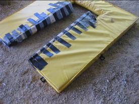
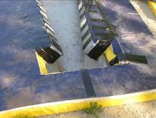
#2 Cantilevered padding systems creates a strong possibility of padding failure as seen in the #3 sample in the photo below. This will leave an unpadded area directly on top of the highly dangerous edge where the top of the side wall meets the runway.
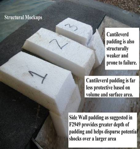
#3 Cantilevered designs create a lack of structural stability; so that the box collar will be prone to sliding out of its correct position, almost always in a rearward direction. By recessing the collar into the bottom of the front bun sections it will be subject to the movements of the entire system! Since no specification currently exists to secure an entire landing system to the ground its performance will be subject to the position of the landing mats which are already chronically too far behind the back of the box.
“5.12 “The pole vault box collar shall be fixed to the ground
or the inner walls during use.” 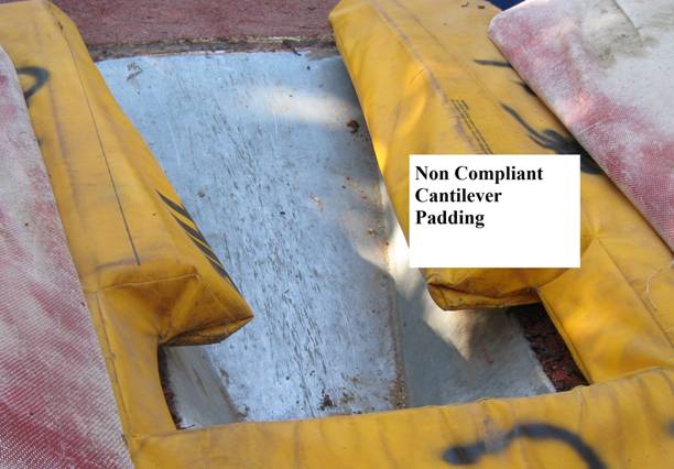
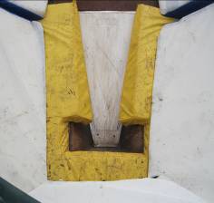
#4 Cantilevered collars tend to narrow the plant able area. The angles along the top inside upper edges of the side wall padding and how far out beyond the top of the side walls edges they extends is extremely important when considering the size of the pole entry area. It appears that the inside walls of the UCS collar are clearly too vertical and do not correctly match the angles of the side walls of the plant box for best shock absorption as demonstrated below: This effect can also be been seen in the mock up #2 below. The taper in #1 is far superior for pole entry then #2 which is more vertical and conforms less to the side wall of the plant box.
F2949
“5.10 The box collar wings shall allow improperly planted
poles to slide forward and downward into the bottom of the
plant box. The wings shall conform to the inner walls of the
plant box so as to provide protection and yet guide a poorly
planted pole to the base of the strike plate at the bottom-rear of
the box.”
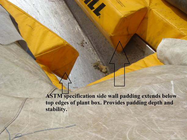
Below~ Note depth of protection on this 2013 version. Thicker padding along the upper side walls means more protection, less padding, or no padding, means less protection. Additionally, note how the wings help to firmly hold the collar into its correct position.
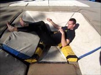
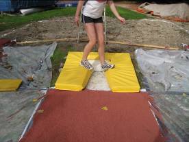
Below - In this 2012 prototype we tested stability and support with vaulter in the most critical potential landing positions.
Depth of padding on the upper side wall areas clearly improves safety in the worst case landing scenarios. Cantilevered collars and those with side wall padding look virtually the same from the top view, but the view from the landing pad is another story.
F2949 structural plan 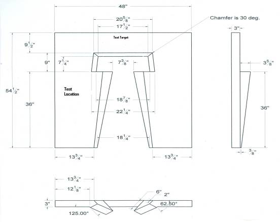
Testing and Prototypes
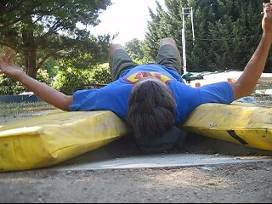
Since 2003 we have experimented and tested many kinds of plant box padding. Mostly we were looking to get rid of the hard places in the worst landing scenarios. Placing padding on the inter-walls was without question the best way. Below are a few of the many possible worst case scenario anatomical positions we tested some years ago.
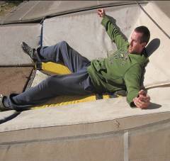
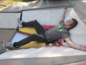
Extending the padding down the interior side walls aids vaulter protection by limiting the amount he/she penetrates into the box. It also increase the distance over which deceleration can occur. This is extremely important when considering many of the worst case landing scenarios. Cantilever padding unfortunately also potentially causes more pressure, on small surface areas, of a pole vaulter’s body as can be seen below: deficient
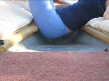
Above~ left Chris Swanson NAIA champ poses anatomically in a classic short landing position on side wall padding. Note how wall and body padding conform to his back and buttocks. Above left, Chelsea Johnson 2009 World Championship Silver medalist, demonstrates cantilever method prototype. Note lack of available padded surface area for shock distribution.
Below~
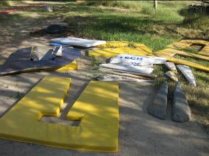
Plant box collar development samples and some and prototype testing we did during the early days of development. It quickly became obvious that more padding is better at distributing shock over a larger surface area and thicker pads. Video available upon request.
Above left~ Elena Clarke SLO HS/ UCLA testing edges and walls 2011. Above right~ the classic hand slip off at TO landing position on to 3” soft winged collar 2010.
2008 Proto experimenting with internal dimensions. Cantilever collar in 2009 (see Kelli photo below)
2007 proto types with 18” front opening and 4” strike plate.
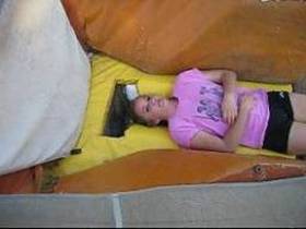
Above~ Kelli (Paso Robles HS) cantilevered collar prototype 2009. Extra padding inserts can be seen peaking out of bend cavity was added to improve depth of padding and side wall angles.